
7 min read
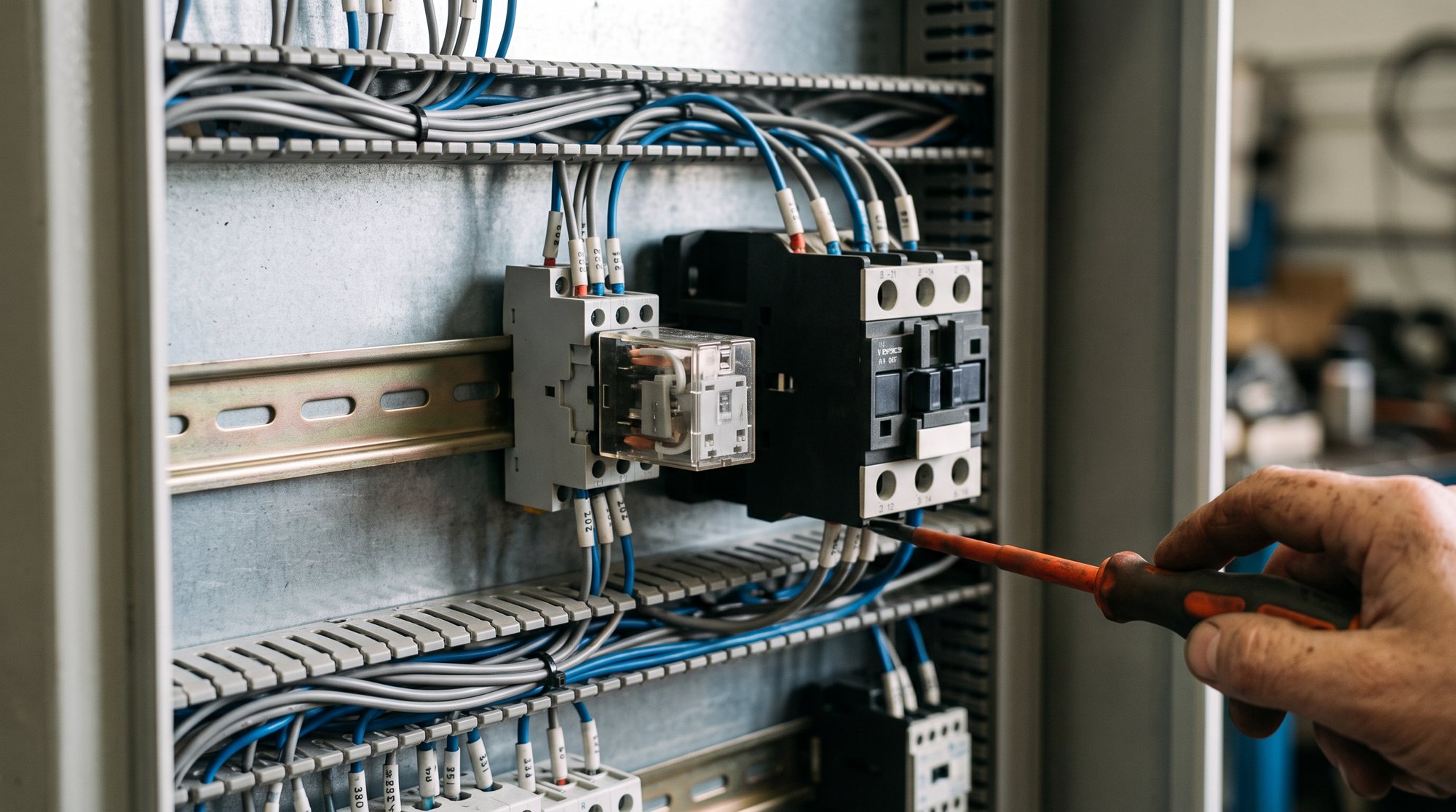
A component has burnt out in the control cabinet of an older packaging machine. The housing shows a coil voltage and, below it, a few contact markings. The colleague from purchasing asks: “So is this a relay or a contactor? And aren’t they the same thing anyway?”
It is a fair question. Both components work on the same principle, and both use a coil to switch contacts. Even so, they are not interchangeable. If you fit a relay where a contactor belongs, you risk welded contacts, a motor that no longer switches off, or a fire in the control cabinet.
This article explains the difference between a contactor and a relay in plain terms: how both work, where they are used, how to recognise them and what you need to specify for a replacement.
The shared principle
Relays and contactors are electromagnetically operated switches. When current flows through a coil, a magnetic field is created. This pulls in a movable armature, and the armature moves the contacts. When the coil voltage drops out, a spring pushes the armature back and the contacts return to their rest position.
The point of it all: a small control current switches a separate circuit. The control circuit and the switched circuit are galvanically isolated from each other. That way a controller running on 24 V DC can switch a load at 230 V or 400 V without the two circuits being electrically connected.
What is a relay?
A relay is built for small currents. It switches signals and control circuits: an indicator lamp, a controller input, the coil of a contactor or a low-power solenoid valve. Typical relays are compact, often plug into a socket and frequently have changeover contacts, i.e. contacts that switch between two positions.
Electromechanical relays are covered by the EN 61810 series of standards. For relays in the control circuits of industrial plants, EN 60947-5-1 also applies, with its utilisation categories for control circuits, such as AC-15 for electromagnetic loads on AC and DC-13 for electromagnets on DC.
What is a contactor?
A contactor is built for switching power. It switches motors, heaters, lighting groups or capacitor banks – in other words, loads with high currents, often three-phase. For this it has three main contacts, usually normally open, plus auxiliary contacts for control and signalling functions.
The crucial difference lies inside. When high currents are switched off, especially under an inductive load such as a motor, an arc forms. A contactor is designed for this: its main contacts usually break the current at two points at once (double break), and arc chutes extinguish the arc quickly. A relay does not have these features.
Contactors for motors and other loads are tested to EN 60947-4-1. This standard defines the utilisation categories that indicate what kind of load a contactor is designed for:
- AC-1: non-inductive or slightly inductive loads, for example resistance heaters
- AC-3: squirrel-cage motors, starting and switching off while running – the most common rating
- AC-4: squirrel-cage motors with inching, plugging or reversing – the toughest duty
A contactor therefore does not have a single rated current, but different values depending on the utilisation category. The AC-1 value is significantly higher than the AC-3 value, because switching off a motor puts far more strain on the contacts.
Contactor and relay compared side by side
| Characteristic | Relay | Contactor |
|---|---|---|
| Task | Switching signals and control circuits | Switching power and loads |
| Typical currents | Milliamps up to a few amps | from a few amps up to several hundred amps |
| Contacts | often changeover, one to four | three main contacts plus auxiliary contacts |
| Arc quenching | no special feature | double break, arc chutes |
| Design | small, often plugs into a socket | larger, on DIN rail or mounting plate |
| Typical load | Controller inputs, indicator lamps, small coils | Motors, heaters, pumps, fans |
| Key standard | EN 61810, EN 60947-5-1 | EN 60947-4-1 |
| Designation in the circuit diagram | usually K with a number | usually Q or K with a number, depending on the edition of the standard |
The in-between case: the contactor relay
Between the two worlds sits the contactor relay, also called a control relay or auxiliary contactor. It looks like a small contactor but has only auxiliary contacts and no main contacts. It is used for interlocks, latching circuits and contact multiplication in control systems. It falls under EN 60947-5-1. If you see a component with lots of auxiliary contacts but no heavy main terminals, you are usually dealing with a contactor relay.
Special cases: safety relays and solid-state contactors
Safety relays
A safety relay is not simply a relay with a different name. It monitors, for example, an emergency stop circuit or a guard door, usually works with two channels and detects its own faults. For safety-related applications, relays with force-guided contacts and contactors with mirror contacts are used. These ensure that a normally closed contact cannot be closed while a normally open contact is welded. A replacement here must always have the same safety characteristics as the original.
Solid-state relays and solid-state contactors
Solid-state relays and solid-state contactors switch with no moving parts, using thyristors or triacs. They work silently, without wear, and are suited to frequent switching cycles, for example with pulsed heaters. On the other hand, they generate heat losses, often need a heat sink and do not provide true galvanic isolation in the off state.
How to tell what is in front of you
If you need to identify a component in the control cabinet, these features help:
- Terminal markings: the main contacts of a contactor are marked 1/L1, 3/L2, 5/L3 on the supply side and 2/T1, 4/T2, 6/T3 on the load side. Coil terminals are called A1 and A2.
- Auxiliary contacts: two-digit numbers such as 13–14 (normally open) or 21–22 (normally closed).
- Nameplate: markings such as “AC-3”, a power rating in kW at 400 V or a rated operational current clearly point to a contactor.
- Terminal size: sturdy screw or cage clamp terminals for thick conductors indicate power contacts.
- Socket: a plug-in component with a retaining clip on a separate socket is almost always a relay.
Typical mistakes when replacing
- Relay instead of contactor: a relay marked “10 A” on the housing is no substitute for a contactor rated 9 A at AC-3. The relay rating usually applies to a resistive load. When a motor is switched off, the contacts weld or burn away.
- Wrong coil voltage: 24 V AC and 24 V DC are not the same. An AC coil on DC can overheat because the inductive reactance is missing. A DC coil on AC often fails to pull in cleanly and hums.
- Looking only at AC-1: the higher AC-1 value tempts people to choose a contactor that is too small for a motor. For motors, AC-3 is what counts, and AC-4 for inching and reversing duty.
- Forgetting the auxiliary contacts: if the normally closed contact for an interlock or the normally open contact for the latching circuit is missing, the control system no longer works as intended.
- Leaving out the suppressor: many contactor coils have an RC element, a varistor or a diode for surge suppression. Without it, controller outputs can be damaged.
Work on the control cabinet may only be carried out by qualified electricians. The basis is the German accident prevention regulation for electrical installations (DGUV Vorschrift 3) and the standard for operating electrical installations (DIN VDE 0105-100). The manufacturer’s instructions and the plant’s circuit diagram take precedence over any general recommendation.
What to specify when ordering a replacement
For a contactor:
- manufacturer and complete order number
- coil voltage and type of voltage (AC with frequency, or DC)
- rated operational current at AC-3 or motor power in kW at 400 V
- number and type of auxiliary contacts, for example 1 NO and 1 NC
- frame size, mounting and connection technology (screw, spring clamp)
- attached accessories such as an auxiliary contact block, surge suppressor or mechanical interlock
For a relay:
- manufacturer and complete order number
- coil voltage and type of voltage
- contact configuration, such as 2 changeover contacts, and switching current
- socket type and pin assignment, if it is a plug-in type
- additional functions such as LED, test button or freewheeling diode
A photo of the nameplate and a photo of the installation with its wiring answer many follow-up questions at a glance. Which parts you should generally keep in stock for the control cabinet is covered in our article on the most important spare parts for the control cabinet. How to set the right protection for the motor is explained in the article setting a motor protection circuit breaker.
When the original part is no longer available
Older plants in particular contain contactors and relays that the manufacturer no longer supplies. You then need a replacement with a matching coil, the same contact configuration and sufficient switching capacity, ideally in the same frame size. KTB Europe, a family business from Hamburg, has been sourcing spare parts of all brands worldwide since 1976. Send us the part number, a photo of the nameplate or a description. For discontinued parts, we look for alternatives that are a technical match.
Find out more on our pages on MRO procurement and discontinued parts. You can send your enquiry via the contact page.
Conclusion
Contactors and relays work on the same principle but are built for different tasks. The relay switches signals; the contactor switches power and copes with the arc when switching off. If you pay attention to coil voltage, utilisation category and auxiliary contacts when replacing, you avoid the typical mistakes and get a component that works reliably in the plant.
Frequently asked questions
Can I use a relay instead of a contactor?
Not for motors and other power loads. A relay has no arc-quenching features, and its current rating usually applies to a resistive load. When a motor is switched off, the contacts can weld or burn away.
What does AC-3 mean on a contactor?
AC-3 is a utilisation category according to EN 60947-4-1. It applies to squirrel-cage motors that are started and switched off while running. The AC-3 current is the most important value when you select a contactor for a motor.
What is a contactor relay?
A contactor relay (auxiliary contactor) looks like a small contactor but has only auxiliary contacts and no main contacts. It is used in control systems for interlocks, latching circuits and contact multiplication. Technically it sits between a relay and a power contactor.
What happens if the coil voltage is wrong?
Too high a voltage, or an AC coil on DC, leads to overheating and can destroy the coil. Too low a voltage, or a DC coil on AC, makes the armature pull in poorly, so the component hums or the contacts bounce. Always check the voltage and type of voltage on the nameplate.
How do I recognise a contactor in the control cabinet?
Contactors have main terminals marked 1/L1, 3/L2, 5/L3 and 2/T1, 4/T2, 6/T3, plus coil terminals A1 and A2. The nameplate shows details such as AC-3 or a motor power in kW. Relays are usually smaller and often plug into a socket.
About the author
Mica Duarte
Senior Procurement Specialist at KTB Europe with over 15 years of experience in global MRO sourcing and supply chain management.
LinkedIn